I recently built a DHC-2 Beaver from Hangar 9 (hangar-9.com). This airplane is designed around the Evolution 33cc two-stroke gasoline engine, but I wanted to add the realism of a Saito three-cylinder radial engine (saito-engines.info). This four-stroke engine not only offers a beautiful engine sound but also adds the benefit of clean and more economical fuel consumption. Installing the Saito radial engine requires a new setup for the fuel-tank system, throttle linkage, and servo installation as well as a few other options regarding the exhaust system. Let’s get down to business!
AIRFRAME MODIFICATION
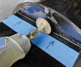
Using a Dremel equipped with a cut-off wheel, the engine box is being trimmed to the proper length required for the Saito 33 radial engine.
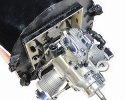
The Saito 33 radial engine has been temporarily secured to the firewall. I used Zap finishing resin to coat all exposed wood areas before the final installation of the engine.
It is important to reinforce critical areas with spruce square or triangular stock. As shown in the photo, example components include the firewall and engine box.
Most giant-scale airplanes feature an engine box built into the fuselage and secured at multiple points for strength. The Beaver is no different. Its engine mounting box features upper, lower, and side frames, and you then glue an already assembled engine box within these frames. This engine box contains the firewall and the bulkheads to secure the included fuel tank. The length of the radial engine (with the included mount) is longer than that of the Evolution engine, so the position of the engine box has to be adjusted. I measured the Saito 33R3’s length from 1/4 inch behind the propeller to the engine mount. I then installed the cowl using that same distance. I marked this dimension with a pencil on the inside of the cowl. This showed the new location for the firewall. I then cut away the excess material from the front of the engine-box structure so that the engine (attached to the firewall) could slip into position. A Dremel Moto-Tool and a cut-off wheel did the job. A sanding block smooths the edges nicely.
I made a firewall template (including the engine mount bolt hole pattern) and worked out the positions for the throttle arm, carburetor venturi, and the fuel and vent lines. I then fabricated the new firewall, laminated together using three layers of 1/8-inch plywood using 30-minute Zap epoxy. For accuracy, I used a drill press for all required holes and openings. I bolted the engine to the firewall with four bolts and 8-32 blind nuts secured behind the firewall with medium Zap. At this point, I tack-glued the firewall into position and secured the cowl to ensure proper alignment. Once the engine was centered and the necessary propeller clearance existed, I traced the firewall’s location onto the inside of the engine box. After removing the engine, I glued the firewall in place using 30-minute Zap epoxy. I then glued 1/4-inch spruce stock around the perimeter of the firewall (both the inside and outside) for added strength.
Because the new firewall is set farther inside the box, I made a new fuel-tank tray to include the throttle servo using 1/8-inch light ply and 1/4-inch square spruce. To keep the installation simple, the tray is the same width as the inner engine box. A bulkhead attaches the bottom of the tray to the floor within the aircraft. I then reinforced everything with the spruce stock cut to length, and I glued it into place.
TIP OF THE MONTH
Keep Cool with Engine Baffles
Keeping your engine from overheating is mandatory for consistent performance. Building baffles within the cowl to ensure that cool air travels through the surfaces of the engine is recommended not only on radial engines but also on all engines. My DHC-2 Beaver included a painted and finished dummy radial engine that fits into the front of the cowl. To provide proper airflow, I marked the three locations of the engine cylinders and made the openings slightly larger than the cylinders. After the dummy engine is installed, be sure to open the bottom of the cowl to provide twice as much air-exit area as the total of the three air-inlet openings.
I traced the perimeter of the tank onto a piece of paper and then made two 1/8-inch light-ply half-moon tank supports to secure the fuel tank to the tray. I glued the tank to the edges of the supports with silicone adhesive to isolate the tank and absorb some of the engine vibration. Once the supports were secured in place, I cut two slots in the floor so that I could use a 1-inch-wide Velcro strap to secure the tank in place. I also retrofitted the included tank with tank-filter clunks from B&B Specialties (bbspecialties.com). These filters prevent foreign particles from entering the engine. Because the Saito engine has an electronic ignition module, I simply wrapped it in some Du-Bro (dubro.com) foam rubber and used Velcro to secure it under the tank floor. The ignition module has three spark-plug leads that fit through an opening that I made in the mount box.
THROTTLE LINKAGE
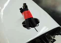
The initial exit for each of the three exhaust pipes has been cut using a Dremel, a cut-off wheel, and a sanding bit. Once the proper location is confirmed, the opening will be enlarged to a perfect circle to allow for proper clearance between the airframe and the exhaust.
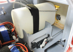
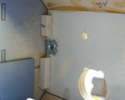
The fuel tank has been installed and is held in place with a single Velcro strap.
I used a 12-inch-long, 4-40 pushrod for the throttle linkage and placed the throttle servo on the tank tray. Making sure that the pushrod was perpendicular to the firewall, I marked the location of the servo and used 1/8-inch light ply to fabricate the servo mount. Once the mount was glued in place, the throttle servo and linkage was properly installed. I typically use ball links when the throttle-linkage geometry is offset. But because I installed the throttle servo in the correct location for a straight linkage installation, I used a standard threaded 4-40 clevis. I cut the pushrod to length and used a Du-Bro 4-40 solder link at the servo arm. For a smooth throttle response, it is important to use your radio’s endpoint adjustment to fine-tune the throttle-servo travel settings. Start at the servo center position, and adjust each of the high and low throw settings so that they are about the same. If the high and low travel values differ by a large amount, the throttle response will not be linear.
MUFFLER INSTALLATION
The Saito 33 radial features three separate exhaust pipes, and the pipes are bent to shape so that they fit through an opening on the bottom of the fuselage. The ends of the pipes are tied together using a bracket that clamps around all of the pipes and is secured to the firewall.
As another exhaust option, Keleo Creations (keleo-creations.com) manufactures an exhaust collector ring for the Saito engine. Just as with full-size engines, the ring directs the exhaust out of the bottom of the airplane. The collector ring has three individual headers that secure to each cylinder. This exhaust system is rigid and greatly simplifies the exhaust installation when the area within the cowl is limited.
FINAL THOUGHTS
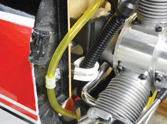
Vibration-damping clamps were used to hold the exhaust pipe away from the engine mount and the throttle pushrod.
Using an engine that’s different than the one your airplane was designed for will require some modifications to the airframe. Using proper, well-thought-out construction and setup techniques will result in an aircraft that will operate properly and last for years.


